Self-contained (SC) luminaires
In an SC system, each emergency luminaire contains its own backup power source. This can simplify installation and limit the consequences of a failure to one luminaire, but inspection and battery replacement may require work on many individual devices. The handbook discusses advantages and limitations for different building sizes.
SC systems with central monitoring
Central supervision enables status messages and tests to be collected and documented remotely. Backup energy is still stored at each luminaire. Monitoring does not replace the responsibility to inspect the system and respond to recorded faults.
Low-power supply (LPS) and central power supply (CPS)
LPS and CPS architectures distribute emergency power from a common battery system to connected luminaires. They can simplify maintenance in larger installations, but introduce requirements for the power supply, circuit separation, fire protection, monitoring and battery room. The correct architecture depends on building use, the number of luminaires, routes and maintenance strategy.
Power supply and wiring
The handbook presents system layouts, local and central monitoring, cable routing and the design of fire-resistant distribution. Examples refer to E30 functional integrity in certain regulations, but the required installation class must always be established for the particular jurisdiction, fire compartment and project.
Rooms, ventilation and protection
Central equipment may require a dedicated location, suitable environmental conditions, fire separation and battery ventilation. Cable protection, fault monitoring and circuit sizing must be assessed together rather than in isolation. The original drawings show example topologies and wiring paths.
EMERGENCY LIGHTING SYSTEMS
Emergency lighting design does not end once the locations and installation methods for emergency lighting have been determined. The appropriate power supply system must also be selected for each project.
The options include luminaires with individual batteries, a central battery system or a group battery system, luminaire operating modes, and the monitoring and testing system. The final, optimal solution for a building depends on the particular project requirements, for which the designer proposes the most appropriate engineering solution.
SELF-CONTAINED SYSTEMS — SC
SELF-CONTAINED SYSTEMS — SC WITH CENTRAL MONITORING
GROUP BATTERY SYSTEM — LPS
CENTRAL BATTERY SYSTEM — CPS
EMERGENCY LIGHTING SYSTEMS 26
+ ADVANTAGES
+ low initial installation cost;
+ decentralised system, each luminaire forms a self-contained system;
Self-contained systems SC (Self Contained).
+ quick, straightforward installation; modularity and easy expansion by adding luminaires;
+ no separate battery room required.
In this type of emergency lighting power supply, luminaires contain their own batteries and all components needed for operation: batteries, charger, control unit and, of course, the emergency luminaire itself. If the normal lighting power supply fails, the luminaire automatically switches to its secondary supply, its own batteries.
Simple luminaires without monitoring (manual testing) must be visually inspected. When the test button is activated, it simulates a failure of the main lighting and the luminaire should light up. Inspection logbooks are maintained manually.
− DISADVANTAGES
Self-contained luminaires with built-in automatic testing continuously indicate the state of the battery and light source by LEDs and automatically conduct weekly functional tests and annual battery-duration tests. Visual checking then replaces the need to press a test button, often requiring a ladder. Inspection records are still kept manually.
− testing requires a physical visit to each luminaire;
− the condition of every luminaire must be recorded manually during every inspection;
− battery life is 2–4 years, depending on the luminaire's location; high and low temperatures shorten battery life (except for LiFePO4 batteries, which may last up to 10 years);
− maintenance costs are higher because batteries need more frequent replacement than in other systems.
+ ADVANTAGES
+ low initial installation cost;
+ decentralised system, each luminaire is independent;
+ quick and easy installation, modularity and easy extension with additional luminaires;
Self-contained SC systems with central monitoring.
+ no separate room required for batteries;
+ the status of the entire system is displayed in one location;
In this system, luminaires have their own batteries but can connect by wire or wirelessly to a central unit. The central unit automatically tests all luminaires, monitors the condition of each individual luminaire and simplifies maintenance: staff no longer have to visit each luminaire separately, and the system automatically maintains the inspection record.
+ testing can be carried out from one location.
In Austria, OVE E 8101 requires central monitoring in buildings with more than 20 luminaires. Croatia has no equivalent statutory requirement, but central monitoring is nevertheless recommended where more than 40 luminaires are installed.
− DISADVANTAGES
− testing requires a physical visit to each luminaire separately; the status of each luminaire must be manually recorded at every inspection;
− battery life is 2–4 years depending on luminaire location; high and low temperatures shorten it (except LiFePO4 batteries with a service life of 10 years);
− maintenance costs are higher because batteries must be replaced more frequently than in other systems.
28 EMERGENCY LIGHTING SYSTEMS
+ ADVANTAGES
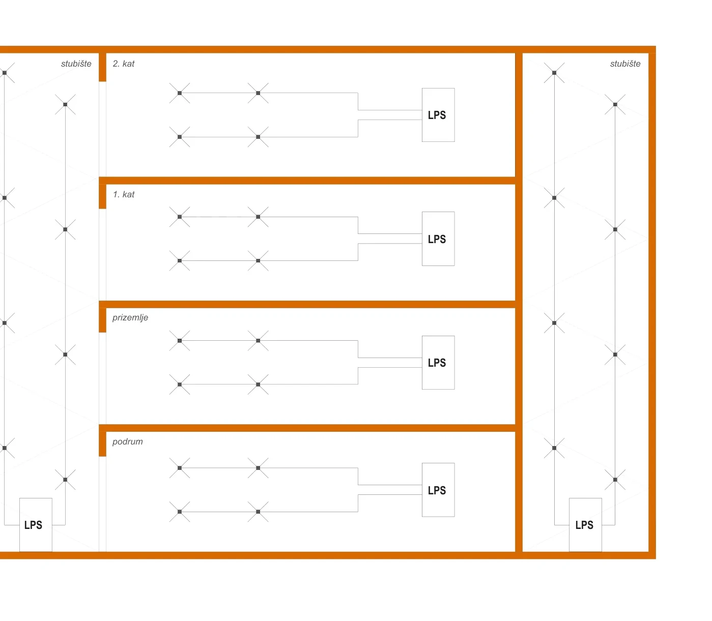
+ a decentralised battery system (LPS) located within a fire compartment does not require fire-resistant wiring;
+ central units can be installed alongside other equipment in technical rooms;
Low-power supply system LPS (Low Power Supply).
+ straightforward servicing and battery replacement;
+ grouping smaller systems makes them easy to interconnect, creating an integrated and functional whole that is ready for future extensions.
A central power supply system with a power limit of 500 W for three hours or 1,500 W for one hour.
The expected service life of LPS batteries is five years at an ideal ambient temperature of 20 °C.
− DISADVANTAGES
− limited installed system power;
− shorter cable runs due to voltage drop (approximately 100–250 m, depending on circuit loading and supply cable cross-section).
Wiring with LPS systems arranged by fire zone:
staircase — second floor
staircase
LPS
first floor
LPS
ground floor
LPS
LEGEND
fire compartment
basement
sub-fire-compartment boundary
electric cable and system line with functional integrity; electric cable and system line without functional integrity
fire protection
LPS
junction box without functional integrity
LPS
LPS
E30 junction box
E30 junction box with fuse
emergency luminaire
emergency luminaire showing evacuation direction
escape route with marked evacuation route
EMERGENCY LIGHTING SYSTEMS 30
Diagram of the low-power supply system (LPS)
+ ADVANTAGES
+ centralised power supply and control make maintenance easier (batteries are accessible and straightforward to maintain);
+ centrally located batteries last much longer than batteries inside luminaires because the environment is less demanding in terms of temperature and proximity to other systems.
Central power supply system CPS (Central Power Supply).
+ virtually unlimited system capacity.
A central supply system provides emergency luminaires with the electrical energy needed in emergencies without a power limitation. This system can be expanded by connecting emergency lighting substations where the main control unit cannot accommodate all luminaires owing to the size or specific features of the building.
+ central monitoring of the system from one location;
+ straightforward connection to fire detection systems, alarm control panels and central monitoring and control systems (CNUS);
+ new-generation battery systems (sealed lead-acid batteries) are safe and emit extremely small amounts of gas.
The expected service life of CPS batteries is ten years at an ideal ambient temperature of 20 °C.
+ system service life exceeding 15 years.
− DISADVANTAGES
− higher initial cost than self-contained battery systems (wiring, accommodation and equipment technology);
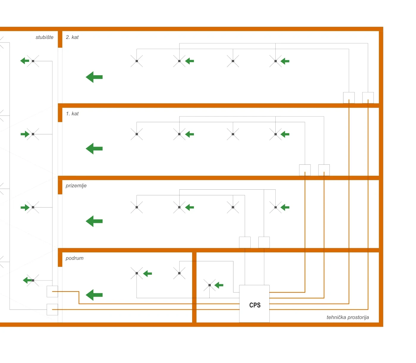
− fire-resistant wiring is necessary; wiring must comply with the regulations for safety systems.
Wiring of a conventional CPS system:
staircase — second floor
first floor
ground floor
LEGEND
fire compartment
basement
sub-fire-compartment boundary
electrical cable and system line with functional integrity; cable and system line without functional integrity
fire protection
junction box without functional integrity
CPS
E30 junction box
technical room
E30 junction box with fuse
emergency luminaire
emergency luminaire with evacuation direction
escape route with marked evacuation path
EMERGENCY LIGHTING SYSTEMS 32
Diagram of the central power supply system
LOCATION OF CENTRAL UNITS AND WIRING OF EMERGENCY LIGHTING SYSTEMS
The rooms and wiring for emergency lighting installations in Western European countries are governed by the relevant national fire protection regulations, namely OVE Guideline R-12-2 in Austria and MLAR in Germany.
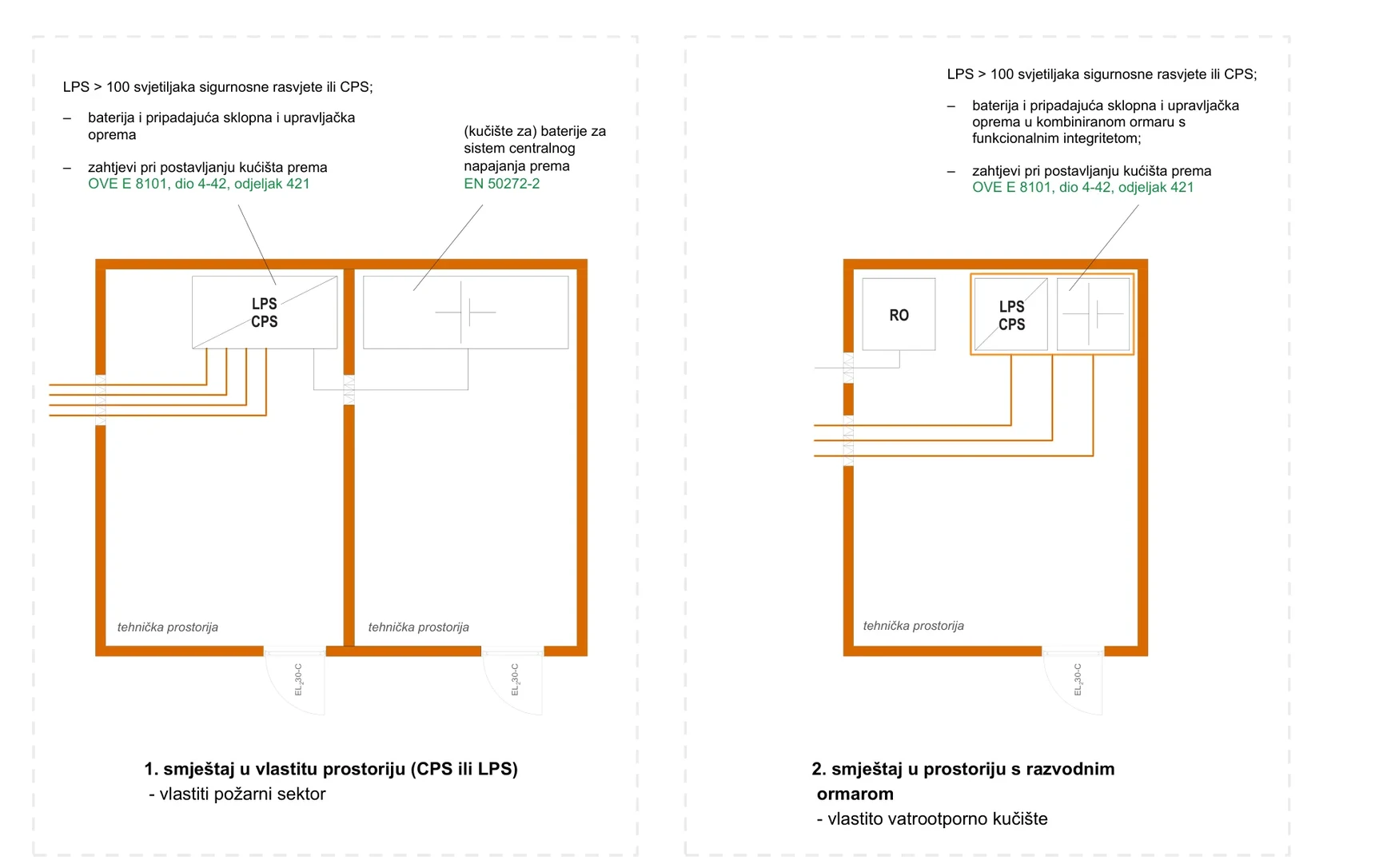
Emergency lighting central units (CPS, LPS) do not always have to be installed in separate rooms; exceptions exist. According to Guideline R-12-2, clause 3.3.1.1, CPS and LPS central units supplying more than 100 luminaires may be located in rooms containing distribution boards if the following requirements are met:
− the emergency lighting central unit is separated from other equipment by its own fire-resistant enclosure E30;
− distribution boards and electrical equipment withstand electric arcs and short circuits (design in accordance with OVE E 8101, Part 4-42, Section 442).
Location of CPS and LPS emergency lighting central units for more than 100 luminaires:
LPS > 100 emergency luminaires or CPS;
LPS > 100 emergency luminaires or CPS;
− battery and associated switchgear and control equipment in a combined enclosure with maintained functional integrity;
− battery and associated switchgear and control equipment;
− battery enclosure for central supply systems according to EN 50272-2;
− enclosure installation requirements according to OVE E 8101, Part 4-42, Section 421;
− enclosure installation requirements according to OVE E 8101, Part 4-42, Section 421.
LPS CPS
LPS CPS
DB
technical room; technical room
technical room
1. Installation in a separate room (CPS or LPS) — its own fire compartment.
2. Installation in a room containing a distribution board — its own fire-resistant enclosure.
LOCATION OF CENTRAL UNITS AND WIRING OF EMERGENCY LIGHTING SYSTEMS 34
Placement of emergency lighting equipment
ROOMS HOUSING LPS EMERGENCY LIGHTING SYSTEMS
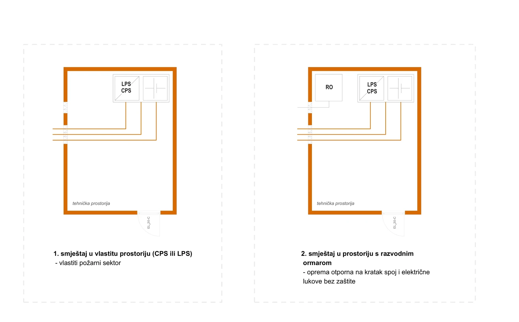
Under R-12-2, Section 4.1, these systems do not require dedicated rooms. They may be located in rooms with distribution boards if all of the following conditions are met:
− the fire compartment being supplied does not exceed 1,600 m²;
− distribution boards and electrical equipment are resistant to arcs and short circuits (according to OVE E 8101, Part 4-42, Section 442);
− no flammable objects are stored in the room.
Location of CPS and LPS emergency lighting central units for fewer than 100 luminaires:
LPS CPS
DB
LPS CPS
technical room; technical room
1. Installation in a separate room (CPS or LPS) — its own fire compartment.
2. Installation in a room containing a distribution board — equipment resistant to short circuits and electric arcs, without additional fire-resistant enclosure.
LOCATION OF CENTRAL UNITS AND WIRING OF EMERGENCY LIGHTING SYSTEMS 36
Examples of equipment installation
WIRING OF CENTRAL EMERGENCY LIGHTING SYSTEMS
In Germany, MLAR, and in Austria, OVE E 8101 require the functional integrity of a room to be maintained for 30 minutes, irrespective of system power and type (clause 5.3.2). The aim is to maintain the operation of the emergency lighting system in the event of a fire. Functional integrity is guaranteed where the installation complies with HRN DIN 4102-12.
The wiring of systems supplying emergency lighting must have at least 30 minutes of fire resistance (E30) up to the first luminaire in the fire compartment. The fire compartment must not exceed 1,600 m².
In fire compartments with more than one emergency luminaire, the luminaires must be distributed alternately across at least two separate circuits. This ensures basic illumination of the escape route even if one circuit fails (HRN HD 60364-5-56, 560.9.2). A maximum of 20 luminaires is permitted per circuit (HRN HD 60364-5-56, 560.9.3).
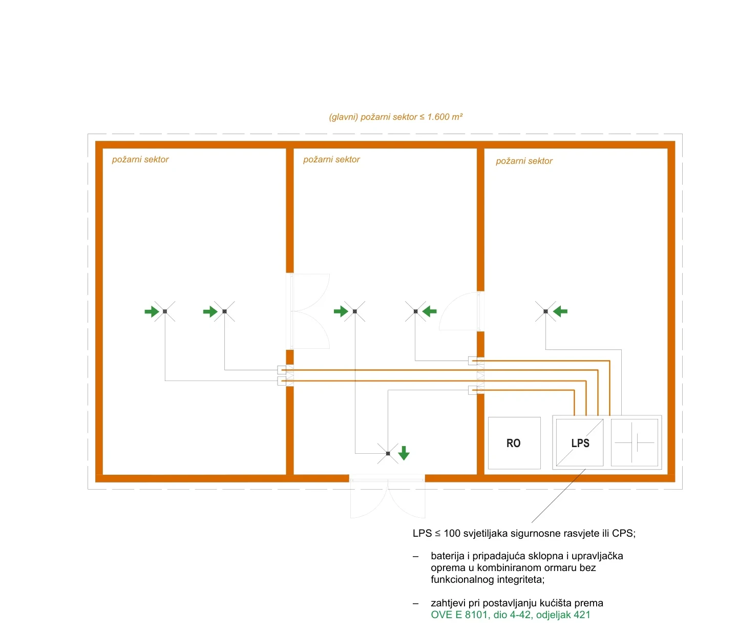
Wiring an LPS system with fewer than 100 luminaires across several fire compartments:
(main) fire compartment ≤ 1,600 m².
NOTE:
fire compartment; fire compartment; fire compartment.
The area of a fire compartment must not exceed 1,600 m².
LEGEND
fire compartment
DB
LPS
sub-fire-compartment boundary
electrical cable and system line with functional integrity; cable and system line without functional integrity
fire protection
junction box without functional integrity
E30 junction box
LPS ≤ 100 emergency luminaires or CPS;
E30 junction box with fuse
− battery and associated switchgear and controls in a combined enclosure without functional integrity;
emergency luminaire
emergency luminaire indicating direction of evacuation
− enclosure installation requirements under OVE E 8101, Part 4-42, Section 421;
escape route with marked evacuation path
LOCATION OF CENTRAL UNITS AND WIRING OF EMERGENCY LIGHTING SYSTEMS 38
System cabling diagram
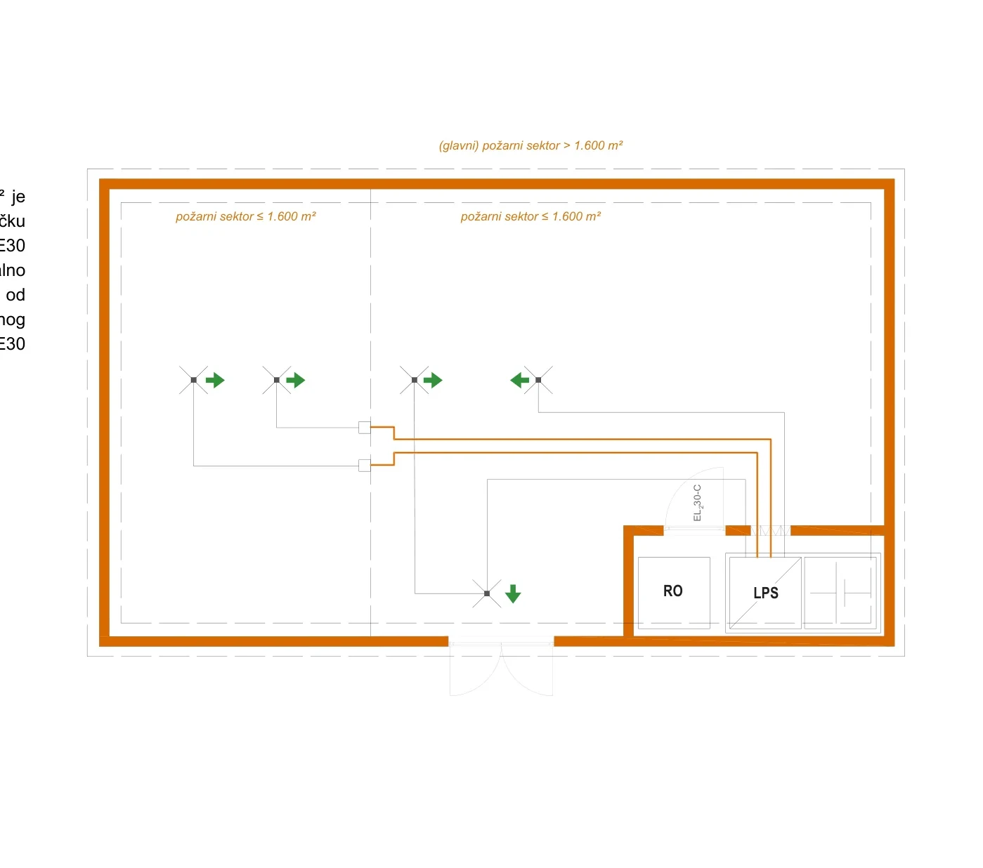
Wiring a fire compartment larger than 1,600 m² with an LPS system:
(main) fire compartment > 1,600 m².
Wiring a fire compartment exceeding 1,600 m² is possible by locating the LPS central unit in a technical room with distribution boards without an E30 enclosure, provided the fire compartment is notionally divided into two fire compartments smaller than 1,600 m². E30 cable must then be installed to the first luminaire or E30 junction box in the notional compartment.
fire compartment ≤ 1,600 m²; fire compartment ≤ 1,600 m².
LEGEND
LPS DB
fire compartment
sub-fire-compartment boundary
electrical cable and system line with functional integrity; cable and system line without functional integrity
fire protection
junction box without functional integrity
E30 junction box
E30 junction box with fuse
emergency luminaire
emergency luminaire indicating direction of evacuation
escape route with marked evacuation path
Cabling – example A
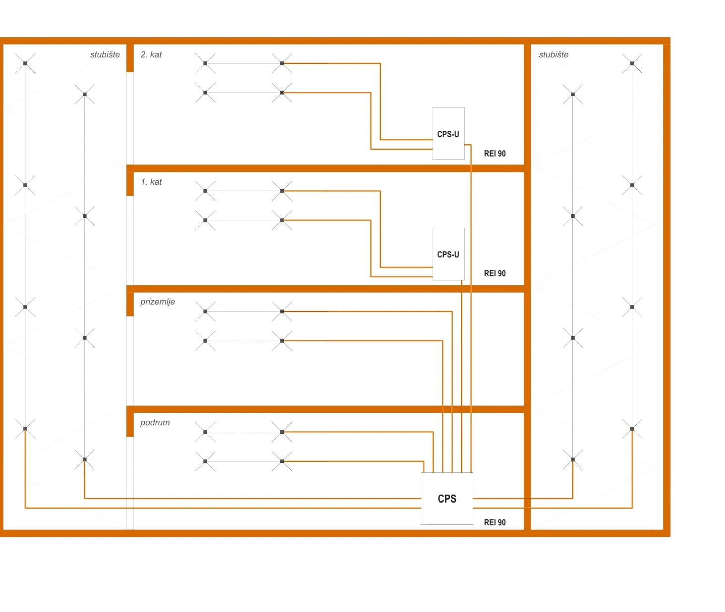
Wiring a CPS system with substations:
staircase; staircase; second floor
NOTE:
CPS-U
REI 90
The staircase and floors are treated as separate fire compartments.
first floor
CPS-U
REI 90
ground floor
LEGEND
fire compartment
basement
sub-fire-compartment boundary
electrical cable and system line with functional integrity; cable and system line without functional integrity
fire protection
junction box without functional integrity
CPS
E30 junction box
REI 90
E30 junction box with fuse
emergency luminaire
emergency luminaire indicating direction of evacuation
escape route with marked evacuation path
LOCATION OF CENTRAL UNITS AND WIRING OF EMERGENCY LIGHTING SYSTEMS 40
Cabling – example B
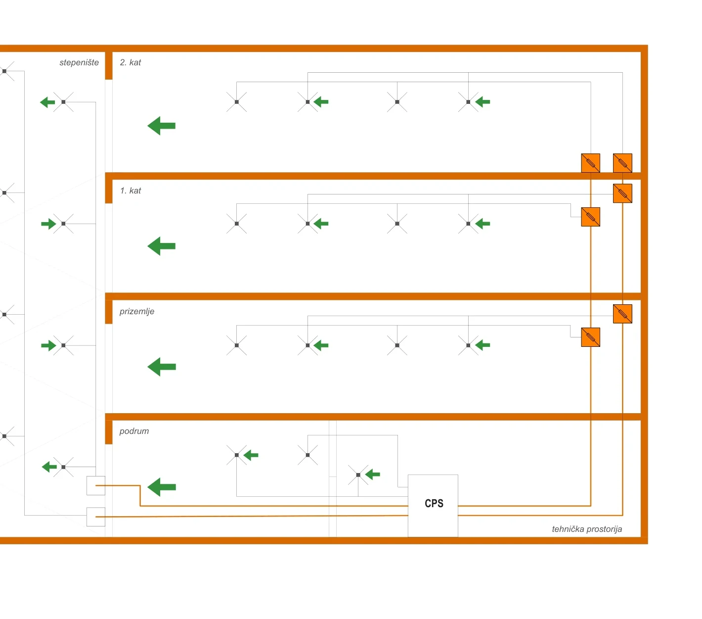
Wiring a CPS system with fused E30 junction boxes:
staircase; second floor
NOTE:
In this example, construction measures consist of separating the floors and staircase into individual fire compartments and using fused E30 boxes.
first floor
ground floor
LEGEND
fire compartment
basement
sub-fire-compartment boundary
electrical cable and system line with functional integrity; cable and system line without functional integrity
fire protection
junction box without functional integrity
CPS
E30 junction box
technical room
E30 junction box with fuse
emergency luminaire
emergency luminaire indicating direction of evacuation
escape route with marked evacuation path
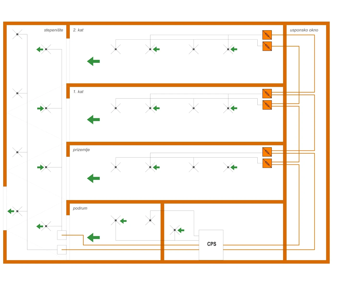
Cabling – example C
staircase; second floor
rising shaft
NOTE:
In this example, the construction measures consist of separating floors and staircases into individual fire compartments, using E30 junctions and routing electrical cables and lines in a type A rising shaft in accordance with fire protection guidelines.
first floor
ground floor
LEGEND
fire compartment
basement
sub-fire-compartment boundary
electrical cable and system line with functional integrity; cable and system line without functional integrity
fire protection
junction box without functional integrity
CPS
E30 junction box
E30 junction box with fuse
emergency luminaire
emergency luminaire indicating direction of evacuation
escape route with marked evacuation path
LOCATION OF CENTRAL UNITS AND WIRING OF EMERGENCY LIGHTING SYSTEMS 42
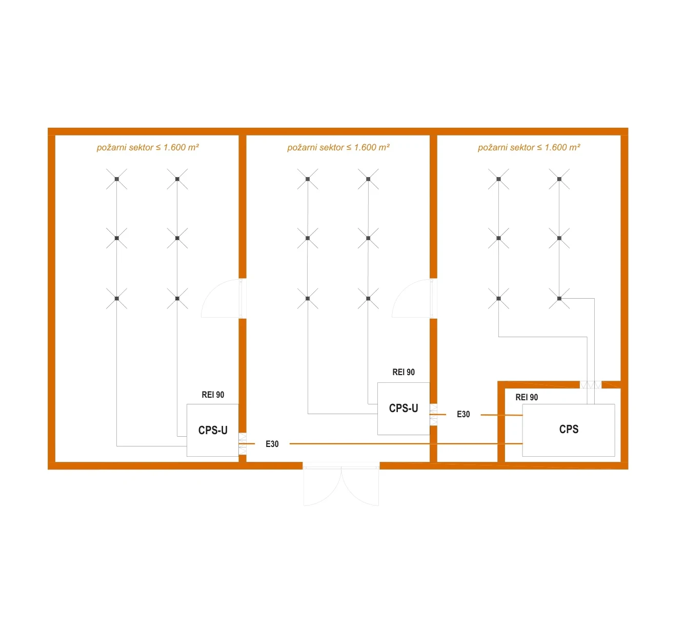
Cabling – example D
Wiring a CPS system from the central unit and substation across several fire compartments:
fire compartment ≤ 1,600 m²; fire compartment ≤ 1,600 m²; fire compartment ≤ 1,600 m²
REI 90
REI 90; REI 90
CPS-U
E30
LEGEND
CPS; CPS-U
fire compartment
E30
sub-fire-compartment boundary
electrical cable and system line with functional integrity; cable and system line without functional integrity
fire protection
junction box without functional integrity
E30 junction box
E30 junction box with fuse
emergency luminaire
emergency luminaire indicating direction of evacuation
escape route with marked evacuation path
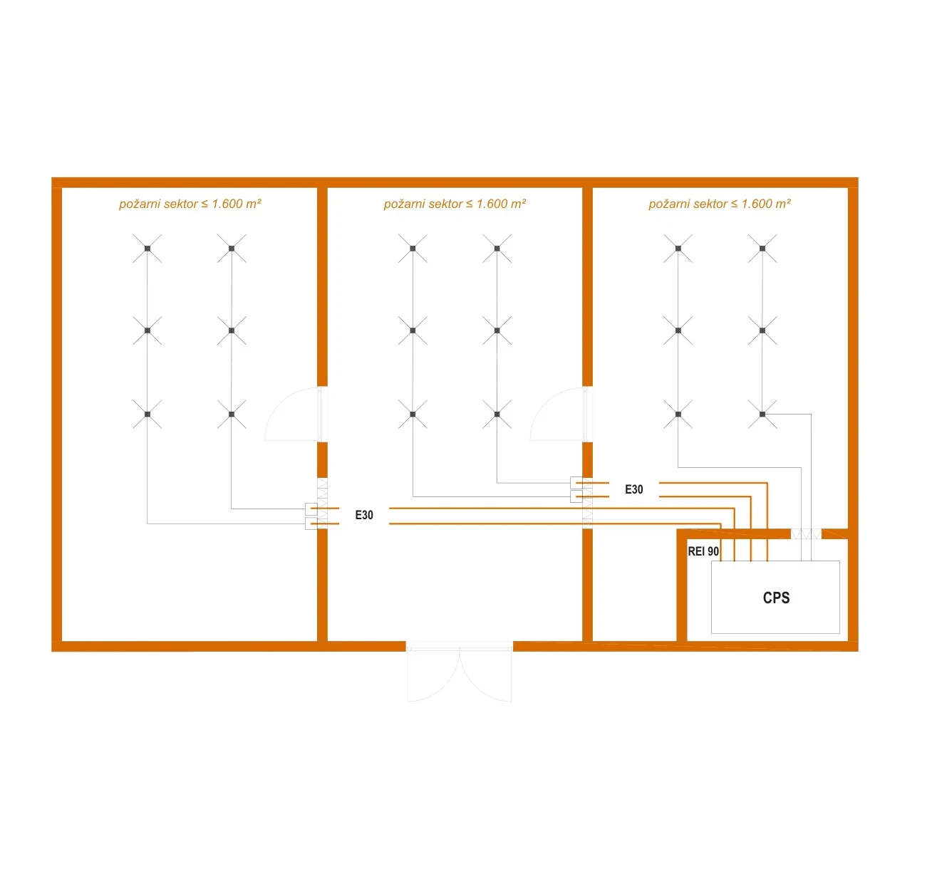
Cabling – example E
Wiring a CPS system across several fire compartments:
NOTE:
The area of a fire compartment must not exceed 1,600 m².
fire compartment ≤ 1,600 m²; fire compartment ≤ 1,600 m²; fire compartment ≤ 1,600 m²
E30
E30
REI 90
LEGEND
CPS
fire compartment
sub-fire-compartment boundary
electrical cable and system line with functional integrity; cable and system line without functional integrity
fire protection
junction box without functional integrity
E30 junction box
E30 junction box with fuse
emergency luminaire
emergency luminaire indicating direction of evacuation
escape route with marked evacuation path
LOCATION OF CENTRAL UNITS AND WIRING OF EMERGENCY LIGHTING SYSTEMS 44
Cabling – example F
Wiring a fire compartment containing no more than two emergency luminaires:
Omitting E30 wiring for the final fire compartment is permitted only where it contains no more than two emergency luminaires and is supplied from an adjacent fire compartment.
LEGEND
fire compartment
sub-fire-compartment boundary
electrical cable and system line with functional integrity; cable and system line without functional integrity
fire protection
junction box without functional integrity
E30 junction box
E30 junction box with fuse
emergency luminaire
emergency luminaire indicating direction of evacuation
escape route with marked evacuation path