Placement and the evacuation concept
The fire-safety study and evacuation concept determine the relevant routes, exits, assembly points and positions of rescue equipment. Emergency lighting must automatically provide the required illumination when the normal lighting supply fails, including local failures. The positioning drawings in the source handbook show typical locations near exits, stairs, changes of level and direction, corridor intersections, first-aid stations and fire-fighting equipment.
Escape route and open-area lighting
Escape route lighting must make the direction of travel and obstacles recognizable. Open-area or anti-panic lighting helps occupants reach an escape route safely. The quantitative lighting criteria, uniformity ratios and measurement planes depend on the area and the applicable edition of HRN EN 1838. The original technical diagrams are available below at higher resolution.
High-risk task area lighting
Where sudden loss of normal lighting can create an additional hazard, emergency lighting supports the safe interruption of dangerous operations. Required illuminance and response time must be assessed for the task; emergency lighting is not intended to enable hazardous work to continue indefinitely.
Safety signs and pictograms
Escape route signs must be visible, unambiguous and correctly positioned. Visibility depends on whether the sign is internally or externally illuminated and on the viewing distance. The original handbook illustrates the relationship between sign height, viewing distance and pictogram design. Keep standardized safety colours for the safety symbols, even when the surrounding website uses a different brand palette.
Low-mounted guidance and adaptive systems
Additional low-mounted direction indicators may assist orientation in smoke or complex layouts. Adaptive or dynamic signs can indicate alternative exits, but must be planned together with the conventional safety lighting concept and the specific system requirements.
POSITIONING EMERGENCY LUMINAIRES
When positioning and designing emergency lighting, all factors that affect its layout and quantity must be considered. One of the most important documents is the fire safety study, which defines the direction of evacuation and required illumination on the basis of applicable laws and regulations. Rescue equipment, including first-aid and fire-fighting equipment, must also be illuminated. Where no fire safety study is available, applicable standards provide the basis for deciding which locations require emergency lighting. HRN EN 1838 provides clear guidance on the key areas and positions to be illuminated and the required illuminance.
When the electrical power supply to general lighting fails, emergency lighting must fulfil the following functions:
▷ illuminate escape routes;
▷ clearly and unambiguously mark escape routes by installing signs indicating directions of movement and exits; pictograms must be installed at a height of at least 2 m, unless technical or spatial restrictions make this impossible, in which case a lower installation height is permitted;
▷ illuminate rescue equipment and ensure it can be readily identified (at least 5 lx vertically);
▷ illuminate large areas so that people can evacuate safely from the building.
Positioning emergency lighting:
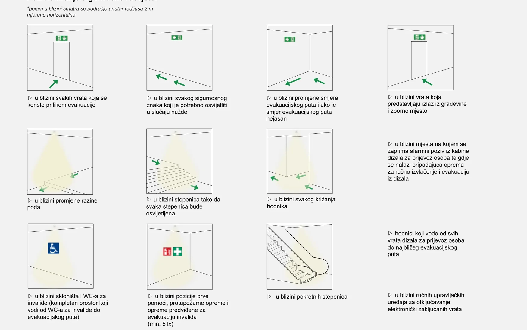
*“Near” means within a radius of 2 m, measured horizontally.
▷ near every door used during evacuation;
▷ near every safety sign that must be illuminated in an emergency;
▷ near changes in the direction of an escape route and where the route direction is unclear;
▷ near doors that serve as exits from the building and lead to an assembly point;
▷ near the location where an alarm call from a passenger lift is received, including the associated equipment for manual extraction and evacuation from the lift;
▷ near changes in floor level;
▷ near stairs, so that every step is illuminated;
▷ near every corridor intersection;
▷ in corridors leading from all passenger-lift doors to the nearest escape route;
▷ near refuges and accessible toilets, including the entire route from the accessible toilet to the escape route;
▷ near first-aid points, fire-fighting equipment and equipment intended for the evacuation of people with disabilities (minimum 5 lx);
▷ near escalators;
▷ near manual controls for unlocking electronically locked doors.
POSITIONING EMERGENCY LUMINAIRES 16
Positioning of emergency luminaires
Additional areas requiring emergency lighting should also be mentioned:
▷ lift cars (according to HRN EN 50172, clause 5.4.2);
▷ technical rooms, to ensure visibility for employees in an emergency.
Lifts pose a problem because being confined in the dark for an unknown period in a small space is not merely uncomfortable: it may adversely affect people who are anxious or suffer from claustrophobia. Consequently, emergency escape lighting as specified for open areas (anti-panic lighting) in HRN EN 1838 must be installed in passenger lifts. Emergency lighting may use its own batteries or be supplied from a central battery system; in the latter case, a fire-resistant power supply (E30) is required.
Emergency escape lighting must be provided in all rooms containing engine-generators, control rooms, switchgear rooms, technical rooms and rooms housing the main equipment for control of general and emergency lighting in the building.
The horizontal illuminance on the floor of these rooms must be at least 0.5 lx. The illuminance on main control equipment and distribution cabinets used for controlling general and emergency lighting must be at least 5 lx at the work-surface plane.
▷ escalators, to enable their safe evacuation;
▷ pedestrian paths in covered car parks.
▷ toilets and changing rooms larger than 8 m² must be equipped with open-area (anti-panic) lighting. Emergency lighting is also recommended in smaller toilet facilities where the route passes through several rooms, an anteroom and similar spaces, to prevent anxiety and allow safe evacuation.
Toilet anterooms must have emergency lighting, as must the entire area leading from the toilet to the escape route.
In accessible toilets, shower cubicles within toilets or changing rooms, and single-occupant toilets with baby-changing areas, a minimum horizontal illuminance of 1 lx must be provided at floor level. In single-occupant toilets equipped with baby-changing facilities, at least 1 lx of horizontal illuminance must also be provided on the changing table.
In toilet anterooms smaller than 8 m², the light emitted by an internally illuminated safety sign (pictogram) may be considered part of the emergency lighting and may contribute to meeting the prescribed requirements.
Note: this provision does not require emergency lighting inside a single-user toilet intended for persons without mobility impairments.
POSITIONING EMERGENCY LUMINAIRES 18
Low-mounted directional markers
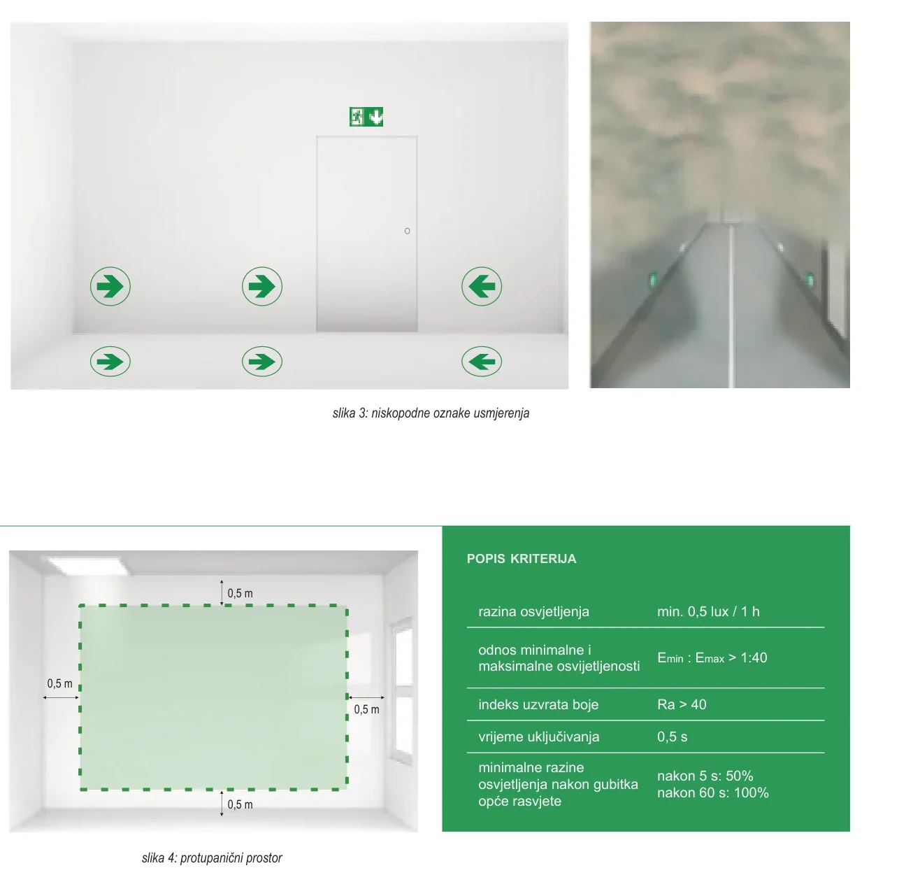
Safety signs (pictograms) are normally mounted at a height of 2 to 3.5 m, but this is sometimes insufficient. In a fire, smoke may obscure signs at that height; low-mounted luminaires are therefore ideal for guiding people towards the building exit. Low-mounted directional markers are installed no higher than 0.4 m. Under DIN 67510, they may be illuminated by LEDs or made of photoluminescent material.
Figure 3: Low-level directional markers.
Open-area (anti-panic) lighting
LIST OF CRITERIA
0.5 m
Minimum illuminance 0.5 lx / 1 h.
It is required in larger rooms (60 m²) or in rooms potentially occupied simultaneously by many people, without clearly defined escape routes.
Ratio of minimum to maximum illuminance Emin : Emax > 1:40.
0.5 m
Colour rendering index Ra > 40.
0.5 m
Switch-on time 0.5 s.
Minimum illumination levels after failure of normal lighting:
after 5 s: 50%; after 60 s: 100%.
0.5 m
Figure 4: Open area for anti-panic lighting.
Low-location guidance and open-area lighting
LIST OF CRITERIA — Escape route lighting
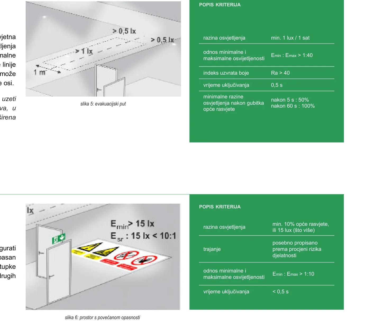
For escape routes up to 2 m wide, luminaires must provide a minimum illuminance of 1 lx (with a minimum-to-maximum ratio of 1:40) at floor level along the centre line of the escape route. The illuminance may fall by 50% at a distance of 50 cm from the centre line.
Minimum illuminance 1 lx / 1 h.
Ratio of minimum to maximum illuminance Emin : Emax > 1:40.
Colour rendering index Ra > 40.
Switch-on time 0.5 s.
Note: wider escape routes must be considered as groups of 2-metre-wide paths; otherwise lighting for extended (anti-panic) areas must be provided.
Minimum illumination after failure of normal lighting:
after 5 s: 50%; after 60 s: 100%.
Figure 5: Escape route.
Emergency lighting in high-risk task areas
LIST OF CRITERIA
Minimum illuminance: 10% of normal lighting or 15 lx, whichever is greater.
Duration: as specified by the risk assessment for the activity.
The aim of lighting in a high-risk task area is to ensure the safety of people involved in a potentially hazardous process or situation, and to allow appropriate shutdown procedures for their own safety and that of others in the area.
Ratio of minimum to maximum illuminance Emin : Emax > 1:10.
Switch-on time < 0.5 s.
Figure 6: High-risk task area.
POSITIONING EMERGENCY LUMINAIRES 20
Escape-route and high-risk task-area lighting
SAFETY SIGNS
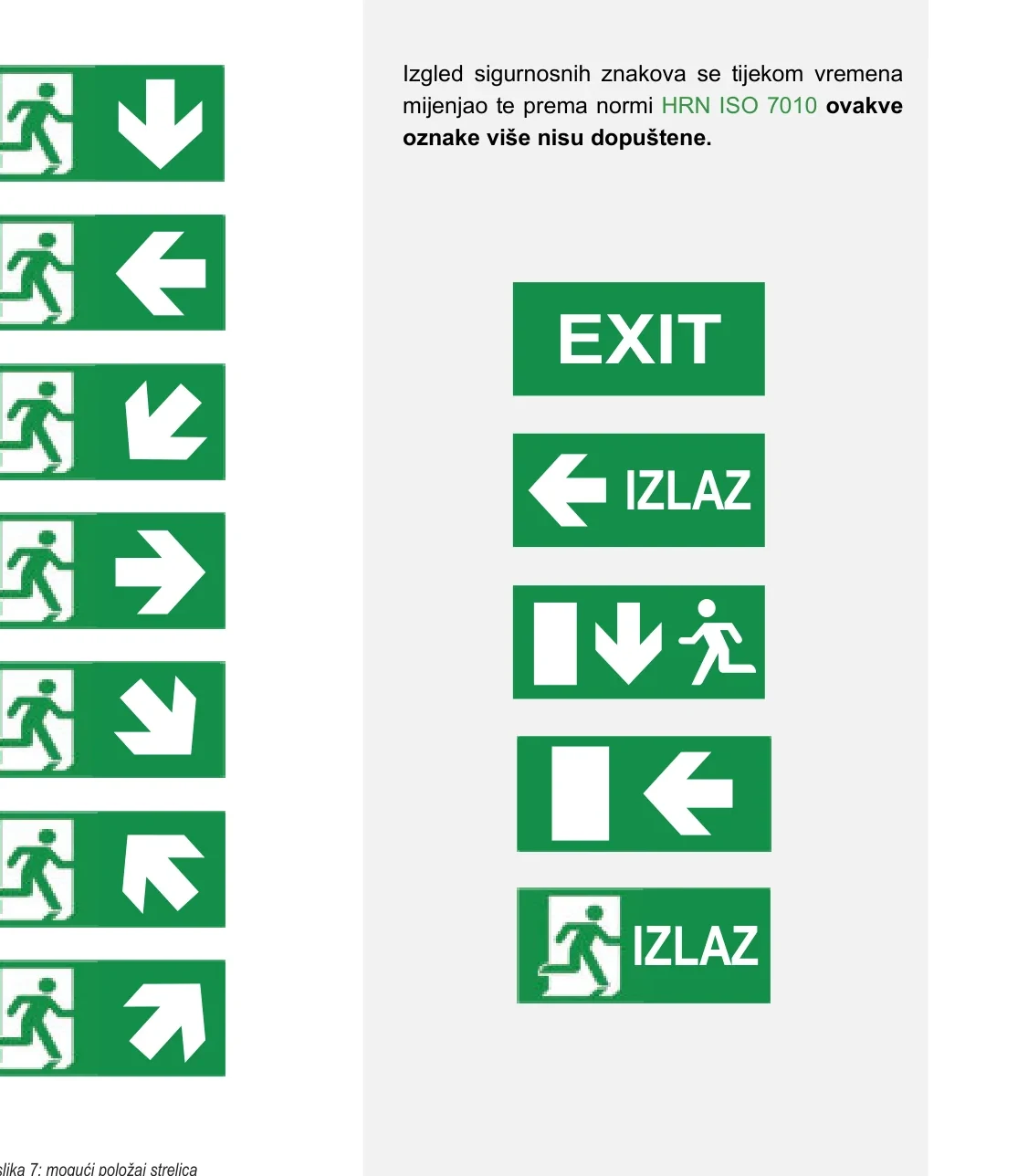
The appearance of safety signs has changed over time; under HRN ISO 7010, signs of the types shown here are no longer permitted.
Safety signs along an escape route must be clearly marked to permit rapid and safe evacuation. They include direction-of-travel signs along the escape route and emergency exit signs. Safety signs must be immediately recognisable and understandable, even under general lighting. They are mounted at a height of 2 to 2.5 m.
EXIT
EXIT
The style and details of escape-route safety signs are predefined in HRN EN ISO 7010. HRN ISO 3864 provides internationally agreed safety sign formats. The design uses a rectangular or square panel with a white pictogram on a green background. Green must cover more than 50% of the sign's total area and its colour must comply with HRN ISO 3864-1.
All safety signs may consist only of the following combination of symbols: the running man and an arrow. Arrows may be rotated in 45° increments.
EXIT
Figure 7: Permissible arrow orientations.
Types of safety signs
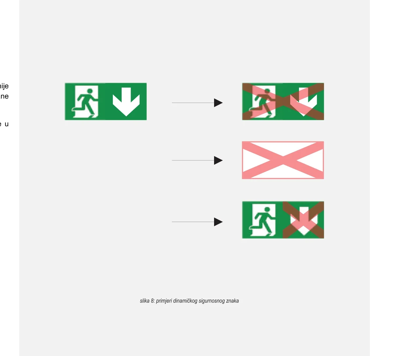
No existing standard or ISO document currently defines a single unambiguous appearance for a dynamically directed pictogram luminaire operating in battery mode.
The examples shown are those most commonly used in practice because they are easy to notice.
Figure 8: Examples of dynamic safety signs.
SAFETY SIGNS 22
Direction and correct use of safety signs
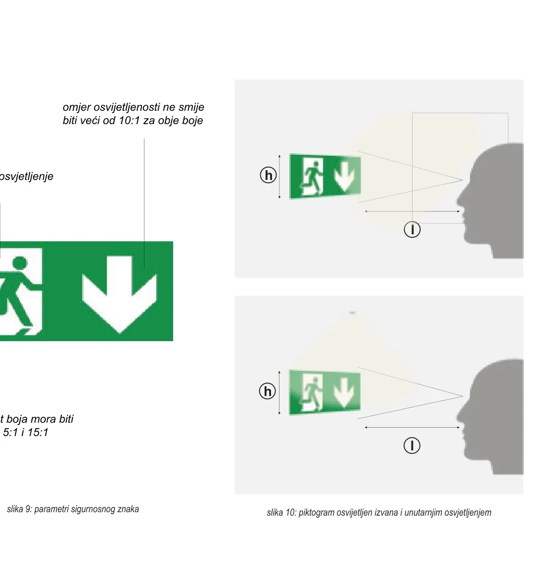
The luminance ratio must not exceed 10:1 for either colour.
Safety signs must comply with HRN ISO 3864, which requires emergency exit and first-aid signs to be safety green with contrasting white. The luminance contrast of white to green must be greater than 5 and less than 15. The minimum luminance of any area of a sign's safety colour must be 2 cd/m². The maximum-to-minimum luminance ratio must not exceed 10:1.
Minimum luminance: 2 cd/m².
The minimum illumination duration for safety signs is one hour. 50% of the required minimum luminance must be achieved within 5 seconds and the full value within 60 seconds.
Colour contrast must be between 5:1 and 15:1.
Figure 9: Parameters of a safety sign.
Figure 10: Externally and internally illuminated pictograms.
Visibility and viewing distance of safety signs
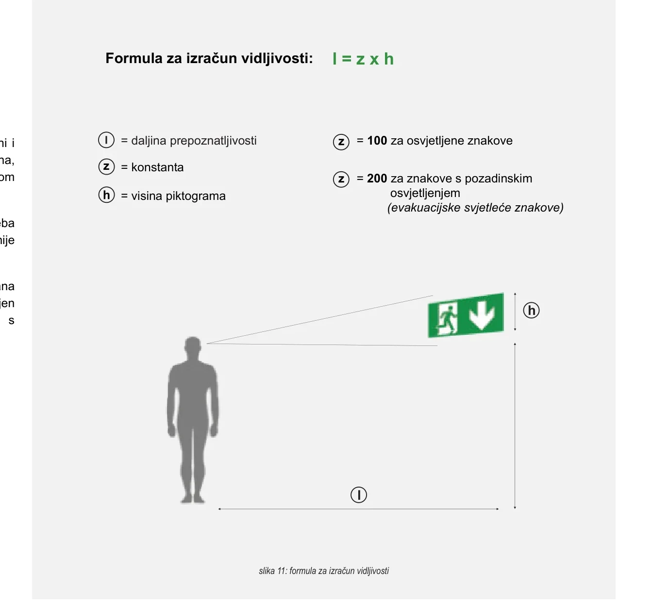
l = z × h — Formula for calculating viewing distance:
Pictograms must be illuminated to remain clear and conspicuous. There are two methods: illumination by an internal or by an external light source.
l = recognition distance.
z = 100 for externally illuminated signs.
z = constant.
z = 200 for internally illuminated (backlit) emergency exit signs.
h = pictogram height.
For easier recognition, the safety sign should be positioned no more than 20° from the horizontal line of sight.
A pictogram 10 cm high is recognisable from a distance of 10 m when illuminated externally, or 20 m when illuminated internally.
Figure 11: Formula for calculating viewing distance.
SAFETY SIGNS
Safety-sign viewing-distance illustration